
Generating Grayscale Images
Generating accurate images with a variety of bit depths is an important requirement for a number of industrial and medical uses for structured light. This note looks at some of the techniques and tradeoffs involved in generating such images on a DMD as well as some of the applications.
The ‘black and white’ images captured by early still and motion cameras effectively used a continuous scale to capture light variations by the use of chemistry to lock in the image. Projecting the images used the same approach.
Moving to digital technologies meant that the gray levels in the images could only have certain values rather than be on a continuous scale. The number of gray levels, or the dynamic range, of a grayscale image is 2 to the power of the number of bits used to encode the image. For example, in an 8-bit image the number of possible gray values a pixel can have is limited to 256, ranging from pure white to pure black. A grayscale image encoded using 12 bits would allow for 4096 gray values or ‘shades of gray’.
For standard color images, it is easy to think of just having three grayscale encoded channels acting together to define each pixel in the image, one each for red, green and blue. If each channel encodes an 8-bit grayscale, then the three channels together make up a 24 bit color image, which is the standard for most computer displays today.
Most computer displays, like LCD displays or the now-dated CRTs, have the ability to display a pixel directly as an intensity defined by the grayscale value. The grayscale value is converted to an analog value like a voltage which sets the pixel intensity.

Digital Micromirror Devices
When using a DMD (Digital Micromirror Device) to generate images however, the situation is very different. The DMD is a binary device that can only generate two grayscale values, white and black. This is because the device consists of a large number of tiny mirrors, one for each pixel and the mirrors only have two states, ‘on’ or ‘off’ and so the DMD can show only a binary image at one time
To create grayscale images, we take advantage of the fast frame rates of the DMD. The DMD that Ajile primarily uses can run at 6,553 binary frames per second with the Ajile DMD controller, or just 153 microseconds per binary frame.
Grayscale Display
To display a grayscale image, we first split the image into its ‘bit planes’; for an 8-bit image, there are 8 such bit planes (or binary images), one representing each of the bits of the original image, from least significant to most significant (as their contribution to the final image). The image below (Figure 1) shows a simple 8-bit gradient pattern and the corresponding 8 bit planes.
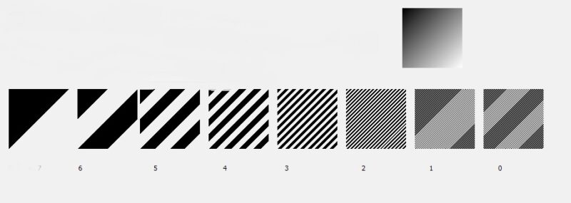
Figure 1: bit planes corresponding to a simple 8-bit gradient pattern.
Generating Grayscale Via Frame Timing
The simplest way to display the 8-bit image would be to display the least significant bit plane for the shortest frame time (153 microseconds for our selected DMD) and then display the more significant bit planes for their power of 2 time, i.e. 2, 4, 8, 16, 32, 64, 128 times the minimum frame time for the remaining bit planes, as illustrated below (Figure 2). The result will be an accurate representation of the 8 bit image.
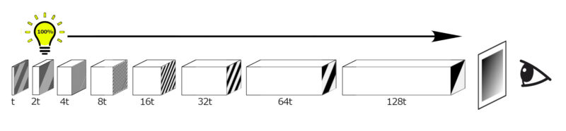
Figure 2: Example of an 8-bit image displayed by maintaining full illumination and altering frame time on the DMD according to bit plane significance. t is the minimum frame time.
Generating Grayscale Via Lighting Intensity
Another approach would be to display each bit plane just for the minimum frame time, i.e 153 microseconds. The full image frame rate would now be 8 * 153 microseconds or 1.2 milliseconds corresponding to 817 full image displays per second.
Of course to make an 8-bit image with 256 gray levels, the intensity level of the least significant bit plane must still be 1/128th that of the most significant bit plane, so we would now need to reduce the illumination in a corresponding way, using the full illumination for the most significant bit plane and reducing it for each less significant bit plane in the sequence, as illustrated in the figure below (Figure 3).
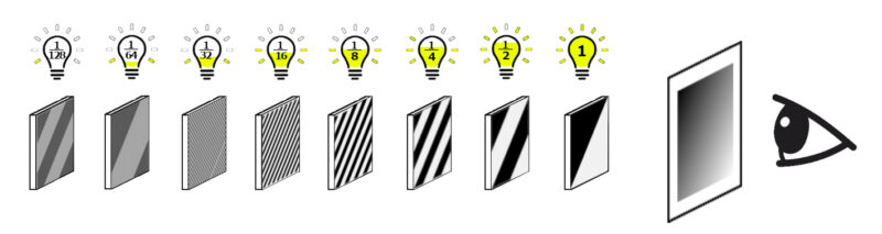
Figure 3: Example of an 8-bit image displayed with equal bit plane times and altering illumination intensity according to bit plane significance
This brings up a few important points: first is that to run fast we need a reliable way of controlling illumination intensity, and second is that the method will generate images that are less bright than the above slower method. In general for this fastest approach the final image brightness will be reduced by 2/n, where n is the number of bit planes; so for an 8 bit grayscale image the final display will only be 1/4 as bright as the slower method described above in Figure 2.
Combining Frame Timing and Lighting Intensity
The Ajile LED controller, as used in the AJP-4500 structured light projector, can control 3 LEDs simultaneously and allows for three methods for control of illumination intensity.
On an individual binary frame basis, each of the three LEDs can each have the drive current set, the on-time set, or can be set to a PWM percentage. This control is handled by a message sent for each binary frame to the LED controller, which has an FPGA to directly manage the LEDs. The shortest on-time supported is 2.5 microseconds. These controls can be combined so that the current can be reduced along with a short on-time so that very low illumination levels are readily achievable.
For other illumination systems, such as laser drivers, the Ajile DMD controller can output accurate, low latency timing triggers with optional delays from the frame start which can be used to modulate external lighting controllers.
With accurate lighting control there are a large number of possibilities available that lie in between the two extremes described above. The less significant bit planes can be displayed for the minimum binary frame time with reduced illumination and the more significant ones can be displayed for longer with the full illumination. This allows for faster frame times and can result in quite small reductions in overall illumination.
For example, consider an 8-bit image displayed at 100 full images per second with reduced illumination on-time for the less significant bit planes when they are displayed for the minimum frame time. The table and associated figure (Figure 4) show the bitplane timings and the corresponding illumination on times.
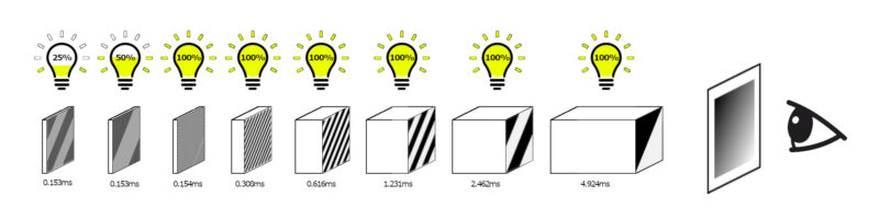
Figure 4 (table and diagram): Example of an 8-bit image displayed by altering both DMD frame time and illumination intensity according to bit plane significance
Adding up the total on-time for the illumination shows that it is on for 98.1 percent of the full image display (which is a very small reduction in illumination efficiency) and yet the frame rate is now one hundred 8-bit images per second, as compared to 25.5 fps with no lighting control. Obviously there are a very large number of trade-offs available between frame timing and illumination efficiency.
The Ajile SDK provides tools to help with these decisions by allowing modelling of different situations with control of frame time, illumination on-time, LED current and the option of dropping least significant bit planes. This is discussed in detail in Chapter 10 of the Ajile Suite User’s Guide.
So far we have focused on discussing 8-bit grayscale outputs. However the Ajile DMD controller, since it operates on a sequence of images and has no constraints imposed by video, does not impose any restrictions on the bit depth of an image or on the binary frame times (other than the minimum frame time of the DMD). This means that images with virtually any bit depth can be displayed and different bit depth images can be mixed anywhere in the sequence.
In this way, a series of binary (1 bit deep) images can be mixed with 4-bit images, 12-bit images, and so on. Color images can also be mixed with grayscale and binary images in the same sequence. In theory, very high bit depth images can be displayed provided the inherent contrast of the projection system can support them.
In the Ajile SDK there is also support for fine tuning the LED illumination based on measurements done with a light meter. The result of such a tuning exercise is shown below (Figure 4) where there is a very good linear relationship between the programmed gray level and the measured light intensity values for 10 bit grayscale display.
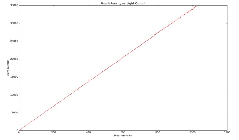
Figure 5: relationship between programmed gray level and light intensity (10-bit grayscale display)
Example Applications of Grayscale Images
3D Imaging
One of the most common uses of structured light is for 3D imaging. A fairly standard approach is to project a series of sinusoidal patterns onto a scene and capture the results with a camera. The inherent quantisation of levels present in 8-bit sinusoids can introduce errors into the results and various techniques such as dithering and defocussing have been used to mitigate this.
The use of 10, 12 or even higher bit depth sinusoids which are still compatible with the fastest camera frame rates can remove this source of error.
Spatial Frequency Domain Imaging (SFDI)
Another important use of sinusoidal patterns is in the medical field where SFDI (Spatial Frequency Domain Imaging) involves projecting these patterns onto human skin and then capturing the results with a camera. This technique allows measurement of the optical properties of the tissue, generation of maps of sub-surface hemoglobin distribution and possibly discovery of clusters of malignant cells.
Psychophysics
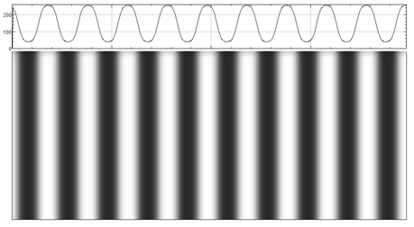
In Psychophysics the use of sinusoidal patterns (or gratings) is common when exploring the human visual system. In many cases use of bit depths greater than 8 is required to yield the required sensitivity in tests since the detection of a grating at the minimum contrast setting is a critical part of the experiment.
Frequently spatial dithering or other techniques are employed to overcome the display limitations. The ability to generate gratings at speed with variable bit depths makes for a very useful tool for testing in the field of Psychophysics.

Example of visual stimuli with different contrasts used in psychophysical testing
3D Printing
Typically in 3D printing when using a DMD to create the pattern, just a binary image is projected using short wavelength light to initiate the photo- polymerization. However, any imperfections or lack of uniformity in the image can result in different degrees of polymerization in different areas of the image and thus the printed part.
The Ajile controller offers the possibility of fine tuning the projected image in order to equalize the energy deposited in each part of the printing area. This can be done by adding a shallow bit depth correction image, for example, say 4 bits deep to the main binary image to fine tune the exposures.
The extra images can be sent in the image stream from the PC or even generated on-board the controller itself. The flexibility of the Ajile Controller makes such arrangements easy to manage.

Color Testing
Until recently most color contrast testing for human vision had been done using CRTs, particularly some special Sony CRTs that had the ability to generate 14-bit grayscale for each of the three colors. The replacement LCDs generally do not have this capability. With the Ajile controller high bit depth color is readily achievable and 36 bit color is very suitable for color contrast testing.
Camera Calibration and Testing
The ability to generate high bit depth monochrome and color images can be very useful for testing and calibration of cameras and sensors. Rather than static images, images with different bit depths and color content can be quickly generated and used as part of automated test procedures
A Note on Higher Frame Rates
One important feature of the Ajile DMD controller is the ability to use a portion of the DMD and not necessarily the full DMD. In this case only the first n columns of the DMD can be used and the frame rate is proportionately faster.
For example, using only the first half of the DMD (i.e. 456 of the full 912 columns) means that the binary frame rate is doubled (from 6,553 binary frames per second to 13,106 fps). By making use of this capability, all grayscale and color frame rates discussed above would also be doubled.
Summary
The Ajile DMD controller offers superior flexibility in creating images with different bit depths, particularly when coupled with the Ajile LED controller to manage projection systems. The DMD controller also provides very low latency triggers to integrate with, or to control other systems.