Edge Consistency in Manufacturing
Accurate dimensional control of thin sheet metal strips is critical in manufacturing processes where edge uniformity directly impacts assembly quality, aesthetics, and performance. Manual measurement methods are time-consuming and prone to inconsistency, especially when assessing long profiles with variable width.
This application note demonstrates how the Ajile DepthScan 3D Imaging System can be used to:
- - Measure the width profile of thin sheet metal strips with sub-millimeter accuracy.
- - Identify regions exceeding dimensional tolerances.
- - Generate 3D reprojection data for manual feedback or automated robotic sanding paths to correct dimensional deviations.
- - Implement a closed-loop feedback system, where reinspection after sanding verifies dimensional accuracy until the part meets specifications.
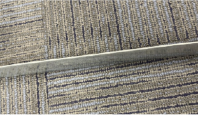
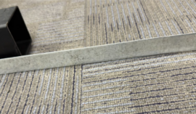
Figure 1: Images of sample sheet metal strips used in this experiment
The Ajile DepthScan 3D Imaging System is a structured-light 3D vision platform capable of capturing millions of high-resolution, color-registered 3D points in under one second. When combined with an industrial or collaborative robot, the system enables closed-loop manufacturing feedback — automatically inspecting, analyzing, and correcting dimensional deviations in real time.
Measurement Workflow
1. 3D Data Acquisition
The sheet metal strip is positioned within the DepthScan’s field of view, and a single scan is captured.
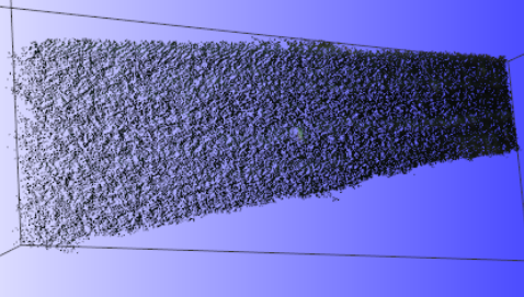
Figure 2: Raw point cloud captured directly from the DepthScan system, depicting the as-scanned geometry prior to analysis.
2. Point Cloud Analysis
Captured data is processed to calculate the average width along the entire strip length. Deviations from tolerance are color-mapped for visualization.
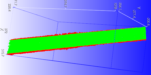
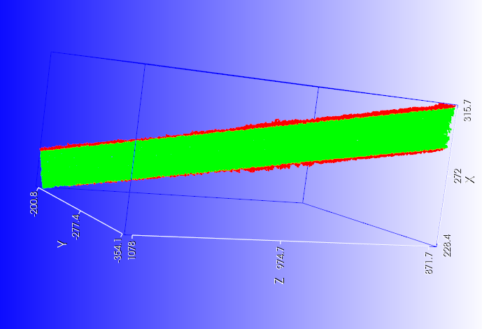
Figure 3: Processed point cloud, where green regions represent the in-spec width and red regions indicate excess material requiring sanding.
3. Reprojection and Robotic Integration
The processed output is converted to either visual feedback in the form of reprojection onto the part, or a robot path plan to remove excess material.
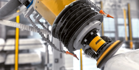
Figure 4: Robotic sander executing sanding path.
4. Closed-Loop Verification
After sanding, the same camera reinspects the part. This closed-loop feedback cycle ensures precision with minimal human intervention
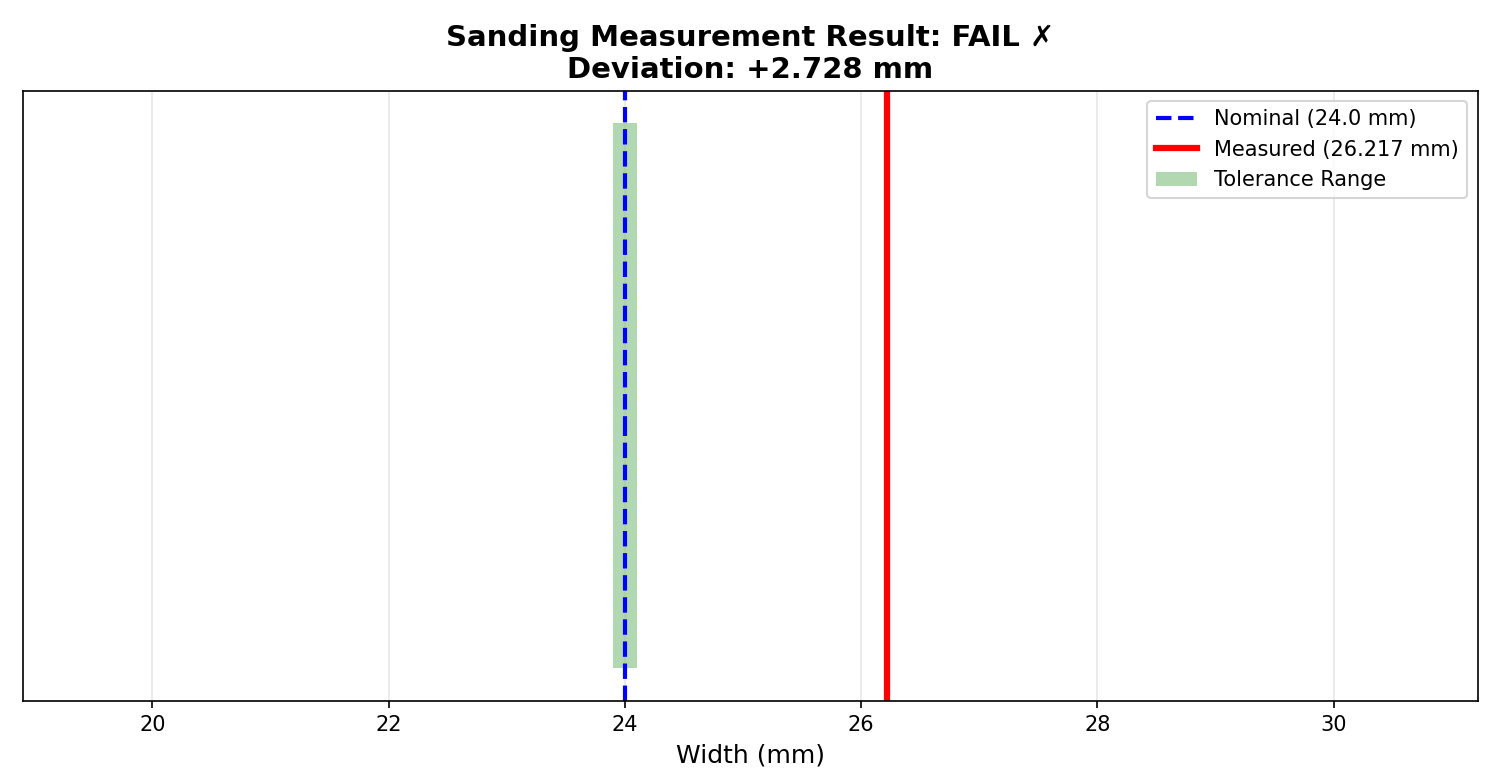
Figure 5: Sanding measurement report outlining nominal width, tolerance and average measurement along long axis of part deviation from nominal.
Conclusion
This application demonstrates how high-resolution 3D measurement combined with reprojection and robotic control enables precise, closed-loop dimensional correction of thin sheet metal parts. By directly measuring the as-built geometry, identifying out-of-tolerance regions, and feeding this information back into manual or automated sanding processes, the DepthScan system enables consistent, repeatable edge control without manual measurement or trial-and-error.
This closed-loop approach improves dimensional accuracy, reduces rework, and enables scalable automation for processes that traditionally rely on manual inspection and correction.